pH Analyzer Calibration Procedure Simulator | Step-by-Step Guide
pH Analyzer Calibration Procedure Simulator
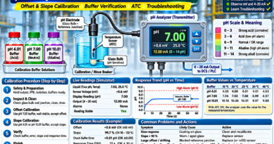
A pH Analyzer Calibration Procedure Simulator is an interactive learning tool designed to explain how to inspect, clean, calibrate and verify an industrial pH analyzer. It demonstrates the importance of buffer solutions, electrode offset, slope adjustment, temperature compensation and calibration verification.
Industrial pH analyzers are widely used in water treatment plants, power plants, chemical industries, pharmaceutical processes and wastewater treatment systems. Accurate pH measurement is essential for monitoring process chemistry, maintaining product quality and protecting equipment.
Using this simulator, you can practise the calibration sequence, observe sensor voltage changes, select different buffer solutions, simulate sensor faults and monitor the corresponding 4–20 mA output.
What Is a pH Analyzer?
A pH analyzer measures the acidity or alkalinity of a liquid by using a pH electrode and an electronic transmitter.
The pH scale generally ranges from 0 to 14:
- pH below 7: Acidic solution.
- pH 7: Neutral solution at the reference temperature.
- pH above 7: Alkaline solution.
A typical industrial pH measurement system consists of a glass electrode, reference electrode, temperature sensor and analyzer transmitter.
The glass electrode develops a voltage depending on the hydrogen-ion activity of the solution. The analyzer converts this voltage into a pH reading and may provide a corresponding 4–20 mA output to the DCS or PLC.
At approximately 25°C, the theoretical electrode response is around 59.16 mV per pH unit. The actual response depends on electrode condition and temperature.
Working Principle of a pH Analyzer
A typical pH measurement system operates through the following sequence.
1. pH Sensor Measurement
The pH electrode is immersed in the process liquid. The glass membrane develops an electrical potential related to the difference in hydrogen-ion activity between the process solution and the electrode’s internal reference system.
2. Reference Electrode
The reference electrode provides a stable reference potential. The analyzer measures the voltage difference between the measuring and reference electrodes.
A blocked or contaminated reference junction can cause unstable readings, slow response or measurement errors.
3. Temperature Compensation
Temperature affects the electrode’s voltage response and the actual pH of buffer solutions.
Automatic Temperature Compensation (ATC) uses the temperature input to compensate for the electrode’s temperature-dependent response.
ATC does not automatically correct every temperature-related change in the process chemistry. Always use the correct temperature-dependent buffer values during calibration.
4. Analyzer Signal Conversion
The analyzer converts the measured electrode voltage into a pH value using its calibration settings.
A common configured output range is:
- 4 mA = pH 0
- 12 mA = pH 7
- 20 mA = pH 14
Actual output ranges and scaling depend on the analyzer configuration.
What Is pH Analyzer Calibration?
Calibration is the process of adjusting the analyzer’s measurement response using known reference buffer solutions.
A typical two-point calibration uses:
Offset Calibration: A pH 7.00 buffer is commonly used to establish the electrode’s zero point or offset.
Slope Calibration: A second buffer, usually pH 4.01 or pH 10.01, is used to determine the electrode’s sensitivity or slope.
The analyzer compares the measured electrode response with the expected response and calculates the calibration parameters.
A poor slope may indicate an ageing electrode, glass coating or other sensor problems.
pH Analyzer Calibration Procedure – Step by Step
The following sequence explains the general calibration process. Actual procedures depend on the analyzer model, electrode design and plant maintenance philosophy.
1. Safety and Preparation
Before starting calibration:
- Inform the control room and obtain the required work permit.
- Follow the approved isolation procedure where sensor removal is necessary.
- Wear appropriate gloves and eye protection.
- Confirm whether the analyzer output must be placed in hold or maintenance mode.
- Prepare fresh pH 4.01, 7.00 and 10.01 buffer solutions as required.
- Use clean beakers and deionised water for rinsing.
- Check the expiry date and storage condition of the buffer solutions.
If the sensor is installed in a pressurised process connection, follow the approved isolation and depressurisation procedure before removal.
2. Inspect and Clean the Sensor
Inspect the glass bulb and reference junction for:
- Process coating or deposits.
- Cracks or physical damage.
- Discolouration.
- Blocked reference junction.
- Cable or connector damage.
Clean the electrode using a method recommended by the manufacturer.
Rinse the electrode with deionised water before placing it in a buffer solution. Avoid rubbing or scratching the glass bulb.
If the electrode is damaged or significantly degraded, replacement may be necessary rather than repeated calibration.
3. Offset Calibration – pH 7 Buffer
The first calibration point is normally the pH 7.00 buffer.
Procedure:
- Rinse the sensor with deionised water.
- Place the electrode in fresh pH 7.00 buffer.
- Ensure the glass bulb and reference junction are properly immersed.
- Allow the reading to stabilise.
- Select the offset calibration function on the analyzer.
- Accept the pH 7.00 reference value according to the analyzer instructions.
The analyzer adjusts the offset so that the measured response corresponds to the known buffer value.
4. Slope Calibration – Second Buffer
After completing the offset calibration, perform the second calibration point.
Common choices include:
- pH 4.01 for acidic measurement applications.
- pH 10.01 for alkaline measurement applications.
Procedure:
- Remove the sensor from the pH 7.00 buffer.
- Rinse it with deionised water.
- Place it in the selected second buffer.
- Wait for the reading to stabilise.
- Select the correct buffer value and temperature.
- Accept the slope calibration.
The analyzer calculates the electrode slope based on the measured response between the two calibration points.
5. Calibration Verification
After calibration, verify the sensor using a suitable buffer solution.
Check the following parameters:
- Buffer reading accuracy.
- Electrode slope.
- Offset value.
- Sensor response time.
- Reading stability.
If the reading is outside the permitted tolerance, investigate buffer contamination, temperature settings, sensor condition and reference junction problems.
Do not assume that a successful calibration automatically proves the complete measurement loop is accurate. Where required, verify the transmitter output and the corresponding DCS or PLC indication.
6. Finish and Restore the Analyzer
After completing calibration:
- Rinse the sensor.
- Store the electrode using the manufacturer’s recommended storage solution if it is removed from service.
- Do not store a typical glass pH electrode dry or in deionised water unless its manufacturer specifically permits it.
- Refit the sensor and restore the process connection safely.
- Confirm that the process measurement is stable.
- Release output hold or maintenance mode according to the approved procedure.
- Inform the control room.
- Record as-found and as-left readings, offset, slope and calibration date.
Explore the pH Analyzer Calibration Simulator
Use the interactive simulator to practise the complete calibration sequence and understand how electrode condition affects measurement accuracy.
1. Safety and Preparation
Complete the safety checklist, including output hold, PPE, isolation requirements and buffer preparation.
2. Inspect and Clean the Sensor
Select different sensor conditions to understand the effect of glass coating, ageing and reference junction blockage.
You can also simulate cleaning or sensor replacement.
3. Perform Offset Calibration
Select the pH 7.00 buffer, wait for the reading to stabilise and accept the offset.
Observe the electrode voltage and displayed pH value.
4. Perform Slope Calibration
Select pH 4.01 or pH 10.01 as the second buffer.
Observe how the analyzer calculates electrode slope and accepts or rejects the calibration.
5. Verify the Calibration
Check the buffer reading, response time, offset and slope. The simulator displays the verification status against its built-in practice limits.
6. Enter Normal Working Mode
After completing the procedure, switch to normal working mode.
You can change the process pH and temperature, simulate acidic or alkaline conditions and observe the analyzer’s displayed pH, alarm status and 4–20 mA output.
Understanding pH Analyzer Calibration Parameters
1. Offset (mV)
Offset represents the electrode’s voltage deviation from its expected reference response. A large offset may indicate electrode ageing, contamination or reference system problems.
2. Slope (%)
Slope represents the electrode’s sensitivity compared with its theoretical response at the applicable temperature.
A reduced slope can indicate a deteriorated or coated glass electrode.
3. Buffer Accuracy
The analyzer reading should agree with the known buffer value within the manufacturer’s specified tolerance.
4. Response Time (T90)
T90 is the time required for the measurement to achieve 90% of the final response following a change in solution.
A slow response can indicate coating, ageing or reference junction problems.
5. Temperature Compensation
Temperature compensation corrects the electrode’s temperature-dependent voltage response. Correct buffer temperature information is also important during calibration.
Common pH Analyzer Problems and Troubleshooting
1. Slow Response
Possible causes include glass bulb coating, an ageing electrode or a contaminated reference junction.
Action: Clean the electrode using the approved method and recalibrate. Replace it if the response remains poor.
2. Low Electrode Slope
Possible causes include electrode ageing, glass membrane deterioration or contamination.
Action: Inspect and clean the sensor. Replace the electrode if the slope remains outside the manufacturer’s acceptable range.
3. Unstable or Drifting Reading
Possible causes include a blocked reference junction, poor electrical connections, damaged cables or electrical interference.
Action: Inspect the reference system, cable and connections. Check the sensor condition.
4. Incorrect Reading After Calibration
Possible causes include contaminated buffer solutions, incorrect buffer selection, inadequate rinsing or incorrect temperature settings.
Action: Use fresh buffers, verify the temperature input and repeat the calibration.
5. Incorrect 4–20 mA Output
Possible causes include incorrect output scaling, transmitter configuration or loop wiring problems.
Action: Verify the analyzer output range, simulate or measure the output as permitted by the approved procedure, and compare it with the DCS indication.
Difference Between pH Calibration and pH Verification
Calibration adjusts the analyzer’s measurement response using known reference buffer solutions.
Verification checks whether the calibrated analyzer measures a known reference solution within the specified tolerance.
Verification helps confirm measurement performance without necessarily changing the calibration settings.
Why Is pH Analyzer Maintenance Important?
Regular maintenance helps maintain measurement accuracy and reduce process-related problems.
Important maintenance activities include:
- Inspect the glass electrode and reference junction.
- Check electrode condition and response time.
- Use fresh and correctly stored buffer solutions.
- Verify temperature compensation.
- Monitor electrode slope and offset trends.
- Check transmitter output and DCS indication.
- Inspect sensor cables and connectors.
- Follow the manufacturer’s cleaning and storage recommendations.
- Maintain calibration records and investigate repeated calibration failures.
Who Should Use This Simulator?
This simulator is useful for:
- Instrumentation and control engineers.
- Instrumentation maintenance technicians.
- Water treatment plant engineers.
- Power plant instrumentation engineers.
- Chemical and process industry technicians.
- Engineering students learning pH measurement.
- Engineers preparing for instrumentation interviews.
It provides a visual and interactive explanation of industrial pH analyzer calibration and troubleshooting.
Important Technical Note
This is a simplified educational simulation of a pH electrode and analyzer. The displayed voltage, buffer values, slope limits, offset limits, response-time limits and 4–20 mA scaling are illustrative model settings. They are not universal manufacturer specifications or approved plant calibration criteria.
Actual buffer values vary with temperature and buffer formulation. Calibration acceptance limits, cleaning methods, storage requirements and output-hold procedures must follow the relevant analyzer and electrode manuals and approved plant procedures.