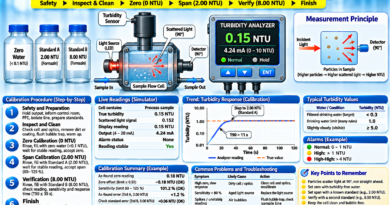
Conductivity Analyzer Calibration Procedure Simulator
Conductivity Analyzer Calibration Procedure: Step-by-Step Guide
A Conductivity Analyzer Calibration Procedure Simulator is an interactive learning tool designed to explain how industrial conductivity analyzers measure the electrical conductivity of liquids and how their sensors are checked and calibrated.
Conductivity analyzers are widely used in power plants, water treatment plants, chemical industries, pharmaceutical facilities and other process industries. They help monitor water quality by measuring the concentration of dissolved ionic substances in a liquid.
This simulator demonstrates the main activities involved in conductivity analyzer maintenance, including sensor inspection, cleaning, temperature compensation, zero checking, cell constant calibration and verification using standard solutions.
You can also simulate common sensor faults, observe conductivity changes, monitor the 4–20 mA output and understand how temperature affects conductivity measurements.
What Is a Conductivity Analyzer?
A conductivity analyzer measures the ability of a liquid to conduct electrical current. The measurement is commonly expressed in microsiemens per centimetre (µS/cm) or millisiemens per centimetre (mS/cm).
Dissolved ions such as sodium, chloride and other salts allow electrical current to pass through the liquid. Generally, a higher concentration of dissolved ions produces higher conductivity.
Conductivity analyzers are commonly used for:
- Boiler feedwater and condensate monitoring
- Demineralised (DM) water quality monitoring
- Reverse osmosis (RO) plant monitoring
- Cooling water monitoring
- Wastewater treatment
- Chemical process monitoring
- Pharmaceutical water systems
Working Principle of a Conductivity Analyzer
A contacting conductivity sensor uses electrodes to measure the electrical conductance of a liquid.
The analyzer applies an alternating electrical signal to the sensor. The liquid between the electrodes allows current to flow, and the analyzer measures the resulting conductance.
The relationship is:
Conductivity = Cell Constant × Conductance
The cell constant depends on the electrode geometry and spacing. It is normally expressed in cm⁻¹.
For example, a conductivity sensor with a cell constant of 1.0 cm⁻¹ and a measured conductance of 1,413 µS produces a conductivity measurement of approximately 1,413 µS/cm.
The analyzer also measures liquid temperature because conductivity changes with temperature. Many water applications use temperature compensation to convert the measured conductivity to a reference temperature, commonly 25°C.
Main Components of a Conductivity Analyzer
1. Conductivity Sensor
The sensor contains electrodes that come into contact with the liquid. It detects the electrical conductance of the sample.
2. Analyzer Transmitter
The transmitter processes the sensor signal, calculates conductivity and displays the measurement.
3. Temperature Sensor
A temperature element, such as an RTD, measures the sample temperature. The analyzer uses this value for temperature compensation when configured.
4. Cell Constant
The cell constant represents the relationship between the electrode geometry and the measured conductance. It is an important sensor parameter used to calculate conductivity.
5. 4–20 mA Output
The analyzer can transmit the conductivity measurement to a DCS, PLC or other control system using a configured analog output range.
Conductivity Analyzer Calibration Procedure
The simulator demonstrates a six-step calibration and maintenance workflow.
1. Safety and Preparation
Before removing or calibrating a conductivity sensor, follow the approved plant maintenance procedure.
Important preparation activities include:
- Inform the control room before starting maintenance.
- Put the analyzer output on hold if required by the plant procedure.
- Wear the required personal protective equipment.
- Isolate the sample flow and depressurise the sensor assembly before removal.
- Allow hot sample lines and sensors to cool.
- Prepare clean containers, deionised water and certified conductivity standards.
- Check the expiry date and temperature information of the standard solutions.
Never remove a sensor from a pressurised or hot process line without proper isolation.
2. Inspect and Clean the Sensor
Inspect the sensor for visible damage, deposits, scaling and contamination.
For contacting conductivity sensors, deposits on the electrodes can affect the measured conductance and cause inaccurate readings.
Typical inspection activities include:
- Check the electrode surfaces.
- Look for scale, oil films and process deposits.
- Inspect the sensor body and cable.
- Check electrical connections.
- Clean the sensor using the method recommended by the manufacturer.
- Rinse the sensor with suitable deionised water.
A damaged sensor should be replaced rather than corrected through calibration alone.
3. Check Temperature Compensation
Conductivity is temperature-dependent. The analyzer may use a temperature sensor and a configured compensation model to convert the measurement to a reference temperature.
For many aqueous solutions, conductivity changes by approximately 2% per °C around a reference temperature. However, the actual temperature coefficient depends on the solution and application.
During this step:
- Compare the analyzer temperature with a reference thermometer.
- Check the temperature sensor and wiring.
- Correct any temperature measurement error according to the manufacturer procedure.
- Verify that automatic temperature compensation (ATC) is configured correctly.
ATC should not be assumed to use a universal 2% per °C coefficient. Use the appropriate compensation model for the process liquid.
4. Check Zero and Calibrate the Cell Constant
The simulator demonstrates a zero check in dry air followed by cell constant calibration using a 1,413 µS/cm standard solution.
In the simulation, the sensor is placed in dry air and the zero is accepted after the reading becomes stable. The sensor is then placed in the standard solution, where the analyzer calculates the cell constant.
In actual field work, the zero procedure is analyzer- and sensor-dependent. Many conductivity systems do not require a routine field zero calibration in air. Follow the manufacturer’s specified procedure.
For cell constant calibration:
- Rinse the sensor with suitable deionised water.
- Avoid contaminating the standard solution.
- Immerse the sensor correctly in the calibration solution.
- Allow the reading to stabilise.
- Enter or confirm the solution’s conductivity at its actual temperature.
- Adjust the cell constant only when permitted by the instrument procedure.
5. Verify with Another Standard Solution
After calibration, verify the sensor using a different certified conductivity standard.
For example, the simulator provides:
- 147 µS/cm
- 1,413 µS/cm
- 12,880 µS/cm
Select a suitable standard based on the sensor range and application.
Check the following:
- Measured conductivity against the certified standard value.
- Cell constant within the manufacturer’s acceptable range.
- Reading stability.
- Sensor response time.
- Temperature measurement and compensation.
Using a second standard helps identify calibration errors that may not be obvious when checking only one solution.
6. Finish and Restore the Analyzer
After calibration and verification:
- Rinse the sensor with suitable deionised water.
- Dry or store the sensor as recommended by the manufacturer.
- Reinstall and secure the sensor assembly.
- Restore sample flow and check for leakage.
- Confirm that the analyzer is displaying a stable process value.
- Release the output hold.
- Inform the control room that the analyzer is back in service.
- Record the as-found and as-left readings, cell constant, standard solution details and calibration date.
The analyzer output should not remain on hold after maintenance is completed.
Explore the Conductivity Analyzer Calibration Simulator
Use the interactive simulator to practise the calibration sequence and understand the relationship between conductivity, conductance, temperature and analyzer output.
1. Follow the Calibration Steps
Select each procedure step and complete the displayed activities.
The simulator includes:
- Safety and preparation checklist
- Sensor inspection and cleaning
- Temperature compensation check
- Zero check in dry air
- Cell constant calibration
- Verification with another standard
- Final restoration checklist
You can use the Next Step, Back, Skip and Go to Start controls to navigate the procedure.
2. Simulate Sensor Faults
Select different practice faults to observe their effect on the analyzer.
The available examples include:
- Fouled or scaled electrodes
- Damaged conductivity cell
- Temperature sensor reading incorrectly
Observe how these faults affect the displayed conductivity and calibration results.
3. Change the Standard Solution Temperature
Adjust the standard solution temperature and observe how the analyzer reading changes.
Compare the temperature-compensated reading with the uncompensated reading. This demonstrates why temperature measurement and compensation are important during calibration.
4. Observe Conductivity and 4–20 mA Output
The simulator displays the conductivity reading and corresponding analog output.
For the example range of 0 to 5,000 µS/cm:
- 4 mA represents 0 µS/cm.
- 12 mA represents 2,500 µS/cm.
- 20 mA represents 5,000 µS/cm.
The actual analog output range must be checked against the configured analyzer settings.
5. Use Normal Working Mode
In normal working mode, change the process conductivity and temperature.
You can simulate:
- High conductivity due to increased dissolved salts.
- Low conductivity due to dilution.
- Changes caused by process temperature.
- Low and high conductivity alarm conditions.
Observe the analyzer display, trend, alarm indication and 4–20 mA output.
Conductivity Sensor Types
Different sensor designs are selected according to the conductivity range and process conditions.
1. Two-Electrode Conductivity Sensor
Uses two electrodes to measure conductance. Commonly used in clean water and low-to-medium conductivity applications. Electrode fouling and polarisation can affect performance in some applications.
2. Four-Electrode Conductivity Sensor
Uses four electrodes to reduce the influence of electrode polarisation and support a wider measurement range. It is used in applications where a conventional two-electrode design may be less suitable.
3. Toroidal or Inductive Conductivity Sensor
Uses electromagnetic coupling rather than conventional exposed contacting electrodes. It is suitable for many high-conductivity, dirty or aggressive liquid applications.
The sensor must be selected according to the process, measurement range, installation arrangement and manufacturer recommendations.
Common Conductivity Analyzer Problems and Troubleshooting
1. Low Conductivity Reading
Possible causes include electrode fouling, incorrect cell constant, sensor damage or an unsuitable installation.
Action: Inspect and clean the sensor, verify the cell constant and check the measurement against a suitable standard.
2. Slow Response
Deposits, coating or a damaged sensor can affect response time.
Action: Clean the sensor using the approved method and repeat the verification test. Replace it if the problem remains.
3. Incorrect Reading During Temperature Changes
A faulty temperature sensor, incorrect temperature coefficient or disabled temperature compensation can cause measurement errors.
Action: Compare the analyzer temperature with a reference thermometer and verify the compensation configuration.
4. Cell Constant Outside the Acceptable Range
This may indicate a damaged sensor, contamination, incorrect calibration setup or an unsuitable standard solution.
Action: Check the sensor condition, calibration solution and procedure. Replace the sensor if it is damaged.
5. Unstable Conductivity Reading
Possible causes include changing sample conditions, air bubbles, poor sensor installation, electrical interference or sensor contamination.
Action: Check sample flow, sensor installation, grounding, wiring and sensor condition.
Important Maintenance Checks
For reliable conductivity measurement, instrumentation technicians and engineers should periodically check:
- Sensor cleanliness and physical condition.
- Sample flow and installation arrangement.
- Temperature sensor accuracy.
- Analyzer configuration and temperature compensation.
- Cell constant and calibration history.
- Standard solution quality and expiry date.
- Analog output scaling and DCS indication.
- Alarm settings and fault indications.
- Sensor cable and electrical connections.
Who Should Use This Simulator?
This simulator is useful for:
- Instrumentation engineers
- Instrumentation technicians
- Power plant maintenance engineers
- Water treatment plant engineers
- Chemical process engineers
- Electrical and instrumentation students
- Engineers learning process analyzers
It provides a visual way to understand conductivity measurement, sensor calibration, temperature compensation and common troubleshooting activities.
Important Technical Note
This is a simplified educational simulator. Its zero-check method, cell constant limits, standard solution values, temperature compensation coefficient, alarm limits, response-time limits and 4–20 mA scaling are illustrative examples.
Actual calibration requirements depend on the analyzer model, sensor design, process liquid, certified standard solution, temperature and manufacturer instructions. Standard solution conductivity values must be taken from the relevant certificate or temperature table.
A dry-air zero check is not a universal requirement for every conductivity analyzer. Likewise, a fixed 2% per °C compensation coefficient is not suitable for every solution.
Always follow the analyzer manufacturer’s manual, approved plant procedure and applicable calibration requirements when working on actual equipment.