Closed Tank DP Level Measurement – Dry Leg Simulator
Inputs: play with these
How the transmitter thinks (live)
Outputs
| Actual level | |
| HP side pressure | |
| LP side pressure | |
| Differential pressure (DP) | |
| Calibrated range (LRV to URV) | |
| Measured level (% of span) | |
| Measured level (mm) | |
| Output current | |
| Measurement error |
Differential pressure (DP) transmitters are widely used to measure liquid levels in closed tanks and pressurized vessels. The dry leg method is suitable when vapour in the tank is unlikely to condense in the LP impulse line.
Working Principle
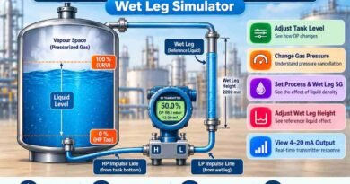
The high-pressure (HP) side connects to the bottom of the tank, while the low-pressure (LP) side connects to the vapour space at the top. Vapour pressure acts on both sides and cancels out, allowing the transmitter to measure the pressure produced by the liquid column.
As the liquid level increases, the differential pressure increases proportionally, provided the liquid density remains constant.
Interactive Simulator
Use this simulator to explore how different process conditions affect level measurement:
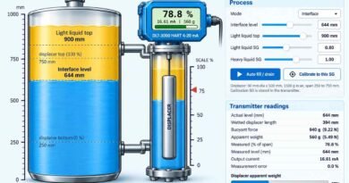
- Liquid level: Observe how the DP changes as the tank fills or empties.
- Vapour pressure: Understand how common pressure on both sides cancels out.
- Specific gravity: See how liquid density affects the DP reading.
- Condensate in the dry leg: Understand how additional LP-side pressure can cause an incorrect level indication.
- 4–20 mA output: Observe how the measured level is converted into a transmitter signal.
Why Is Dry Leg Measurement Important?
Condensate accumulation in the LP impulse line adds hydrostatic pressure to the reference side, potentially causing the indicated level to be lower than the actual level. Understanding this effect helps instrumentation engineers troubleshoot measurement errors and maintain reliable level indication.
Conclusion
Explore the Closed Tank DP Level Measurement – Dry Leg Simulator to understand pressure calculations, transmitter response, and common measurement errors through interactive learning.
Note: This simulator is intended for educational purposes. Actual transmitter calibration and installation depend on the process conditions and instrument configuration.