LP Bypass Simulator – Thermal Power Plant
LP Bypass System in a 600 MW Thermal Power Plant – Working Principle and Simulator
The LP bypass system is an important part of the steam cycle in a thermal power plant. It helps manage the steam flow during turbine start-up, load changes, load rejection and turbine trip conditions.
In a 600 MW thermal power unit, the HP bypass and LP bypass work together. The HP bypass diverts main steam to the reheater, while the LP bypass provides an outlet for the reheated steam and sends it to the condenser after spray-water cooling.
If the LP bypass does not open when required, hot reheat pressure can increase rapidly. This may also affect the HP bypass operation and can lead to high steam pressure, safety valve lifting or boiler protection action.
This simulator helps you understand how the LP bypass system responds to different operating conditions and what can happen when the system does not work properly.
What is an LP Bypass System?
The LP bypass system is designed to divert steam from the hot reheat line directly to the condenser, bypassing the intermediate-pressure and low-pressure turbine sections.
During normal operation, steam flows through the reheater and then enters the IP/LP turbine. But during start-up, sudden load reduction or turbine trip, the turbine may not be able to accept the full steam flow.
At that time, the LP bypass valve opens and directs the excess steam to the condenser. Spray water is used to reduce the steam temperature before it enters the condenser.
The main purpose is to control reheat pressure and temperature while protecting the turbine and condenser.
How HP and LP Bypass Work Together
Both bypass systems have different functions, but their operation is closely connected.
HP bypass:
- Diverts main steam from the boiler outlet to the cold reheat line.
- Helps maintain main steam pressure when the turbine cannot accept the required steam flow.
- Sends steam through the reheater.
LP bypass:
- Receives steam from the hot reheat line.
- Controls hot reheat pressure by diverting excess steam to the condenser.
- Uses spray water to reduce steam temperature before it reaches the condenser.
Think of it this way: the HP bypass provides an alternative route for main steam, and the LP bypass provides an outlet for the steam after reheating.
If the LP bypass fails to open during a turbine trip, steam can accumulate in the reheat system. Hot reheat pressure may rise, and the HP bypass may be forced to close depending on the protection logic.
LP Bypass Working Principle
The LP bypass control system normally operates in automatic mode.
The pressure controller monitors hot reheat pressure and adjusts the LP bypass valve position to maintain pressure near its setpoint.
In this simulator, the LP bypass setpoint follows the unit load. A simplified operating relationship is used, with the LP bypass setpoint maintained around 0.3 MPa above the load-related tracking pressure.
When hot reheat pressure increases, the controller increases the valve opening. More steam is then diverted to the condenser, helping to reduce the pressure.
When the pressure decreases, the valve gradually closes.
The actual control strategy, setpoint calculation and protection logic can vary between power plants and equipment manufacturers.
Why Spray Water Is Required
Steam coming from the hot reheat line has a high temperature. It cannot be sent directly to the condenser without considering the condenser’s allowable operating conditions.
Spray water is injected into the bypass steam line to reduce its temperature.
The spray-water system is therefore an important part of LP bypass operation. If spray water is lost, the LP bypass may close to protect the condenser and downstream equipment.
The simulator includes a spray-water failure event. You can activate it and observe how the LP bypass responds.
LP Bypass Fast Open and Fast Close Conditions
The LP bypass valve does not always depend only on the normal pressure controller. Certain operating and protection conditions can demand a faster response.
Fast open conditions
In this simulator, fast opening is initiated by conditions such as:
- Turbine trip.
- Load rejection.
- HP bypass opening.
- Rapid rise in reheat pressure.
- Manual fast-open command.
During fast opening, the valve moves quickly towards a high opening position. This gives the reheat steam another path to the condenser.
Fast close conditions
The simulator includes the following fast-close conditions:
- High condenser pressure.
- High condenser inlet temperature.
- Loss of spray water.
- Low hot reheat pressure under the modelled conditions.
- Manual fast-close command.
- Condenser vacuum protection trip.
When a fast-close condition is active, the LP bypass valve closes and opening is blocked while the condition remains active.
These are simplified training conditions. Actual plant protection logic, permissives, delays and trip settings must always be checked from the approved plant documents.
What Happens During Turbine Trip?
A turbine trip is one of the important situations where the bypass system becomes very important.
When the turbine trips, the steam flow through the turbine reduces suddenly. The HP bypass may open to divert main steam towards the reheater.
At the same time, the LP bypass should provide a suitable outlet for the hot reheat steam.
If the LP bypass opens correctly, steam can flow to the condenser through the bypass line, subject to condenser pressure, temperature and spray-water permissives.
But what happens if the LP bypass remains closed?
- Steam continues entering the reheat system through the HP bypass.
- The hot reheat pressure starts increasing.
- If the pressure reaches the modelled HP bypass protection limit, the HP bypass is forced shut.
- Main steam pressure can then start increasing.
- Safety valves may lift, and boiler protection may initiate a master fuel trip if the relevant conditions are reached.
This is why LP bypass availability and correct operation are important during turbine trip conditions.
How to Use the LP Bypass Simulator
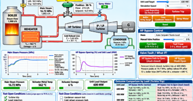
The simulator provides a simplified dynamic model of a 600 MW thermal power unit. You can change the operating load, select different events, operate the LP bypass and compare the results.
1. Change Unit Load
Use the unit load slider to select an operating condition between 180 MW and 600 MW.
Observe how the hot reheat pressure setpoint changes with load. You can also see the current load, HP bypass flow and LP bypass flow.
2. Select Simulation Speed
You can select:
- 1x – Normal simulation speed.
- 5x – Faster simulation.
- 20x – Very fast simulation.
A higher speed helps you observe pressure changes and protection actions in less time.
3. Try Load Rejection
Click the Load Rejection (House Load) button.
The simulator reduces the unit load towards the modelled house-load condition. Observe the HP bypass opening and the LP bypass response.
Check how the hot reheat pressure changes during the event.
4. Try Turbine Trip
Click Turbine Trip to simulate a sudden turbine trip.
Observe the following parameters:
- Hot reheat pressure.
- LP bypass valve opening.
- HP bypass valve opening.
- Main steam pressure.
- Condenser pressure.
- Reheat safety valve status.
- Boiler trip status.
This is a useful scenario to understand why the LP bypass must respond correctly when the turbine trips.
5. Simulate Loss of LP Spray Water
Click Lose LP Spray Water.
The simulator removes spray-water availability. Observe the fast-close response and how the LP bypass valve position changes.
Click the same button again to restore spray water.
6. Simulate Condenser Problems
You can test two condenser-related events:
- Circulating Water Pump Trip: Reduces the available circulating-water capacity in the model.
- Condenser Vacuum Loss: Simulates a loss of condenser vacuum.
Watch the condenser pressure and the LP bypass fast-close response.
7. Operate LP Bypass Manually
Select the required mode from the LP bypass control section.
The available modes are:
- Auto – Setpoint tracks load.
- Auto – Fixed setpoint.
- Manual – Valve position controlled using the slider.
In manual mode, change the valve position and observe the effect on reheat pressure and condenser conditions.
8. Try Fast Open and Fast Close
Use the manual fast-open and fast-close buttons to observe the valve’s quick response.
Compare the valve movement with its normal pressure-control operation.
9. Simulate LP Bypass Valve Failure
The simulator includes two valve fault scenarios:
LP bypass fails to open (stuck closed)
The valve remains closed even when the system requires it to open. During a turbine trip, this can cause hot reheat pressure to rise.
LP bypass stuck open
The valve remains partially open in the simulator. Steam continues flowing towards the condenser, which can reduce reheat pressure and increase the condenser load.
You can clear the simulated fault using the repair button.
10. Compare Different Unit Loads
The outcome comparison section allows you to compare turbine trip or load rejection at:
- 600 MW
- 450 MW
- 300 MW
- 180 MW
The simulator compares a normal LP bypass condition against an LP bypass stuck-closed condition.
It also displays the pressure peaks and protection events predicted by the simplified model.
Important Parameters Used in the Simulator
The simulator uses the following illustrative values for training:
- HP bypass capacity: 760 t/h.
- LP bypass capacity: 900 t/h.
- Full-load hot reheat pressure: approximately 3.4 MPa.
- LP bypass tracking setpoint: approximately 0.3 MPa above the load-related pressure.
- HP bypass forced-close pressure: 4.5 MPa.
- Reheat safety valve pressure: 5.2 MPa.
- Boiler trip pressure: 5.8 MPa.
- LP bypass condenser-pressure closing limit: 20 kPa absolute.
- Condenser pressure trip value: 35 kPa absolute.
- Condenser inlet temperature limit: 90°C.
These values are used only for the simulator’s simplified teaching model. They are not universal operating or protection settings.
What You Will Learn from This Simulator
After using the simulator, you should have a better understanding of:
- The difference between HP bypass and LP bypass.
- How hot reheat pressure is controlled.
- Why spray water is required in the LP bypass line.
- How the LP bypass responds during turbine trip and load rejection.
- Why condenser vacuum and pressure are important.
- How loss of spray water affects bypass operation.
- What can happen when the LP bypass valve fails to open.
- How a stuck-open valve can affect the condenser.
- How bypass operation changes at different unit loads.
Important Note
This is an educational simulator based on a simplified dynamic model. The calculated pressure, flow, valve movement and protection responses are intended to explain the general operating concept. They should not be treated as actual plant performance predictions or operating instructions.
Actual LP bypass control logic, valve capacity, spray-water requirements, condenser limits, interlocks and trip settings depend on the turbine design, boiler configuration, bypass manufacturer and approved plant documents.
Always follow the OEM manuals, approved operating procedures and plant safety instructions when working with real equipment.
Try the LP Bypass Simulator and observe how the HP and LP bypass systems work together during different operating conditions.