DP Flow Measurement Simulator – Learn All Primary Elements
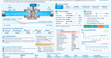
A differential pressure (DP) flow meter has two parts: a primary element in the pipe that creates a pressure difference when fluid flows, and a DP transmitter that measures it. Flow is proportional to the square root of the DP. This simulator covers every common primary element: orifice plates, nozzles, venturis, wedge, V-cone, pitot tubes, airfoil, elbow and the laminar flow element. Pick an element, change the flow, the fluid and the installation, and see what each one is good and bad at.
From flow to 4-20 mA (signal chain)
How it works
About this primary element
| Shape and idea | |
| Typical accuracy | |
| Turndown (usable flow range) | |
| Permanent pressure loss | |
| Straight pipe needed upstream | |
| Best for | |
| Weak point |
1Choose a primary element
2Change the flow
3Design, fluid and installation
Transmitter readings
| True flow | |
| Velocity and Reynolds number | |
| Throat / element size | |
| Differential pressure (DP) | |
| DP at full flow (design) | |
| Permanent pressure loss | |
| Flow read by transmitter | |
| Measurement error | |
| Noise uncertainty at this flow | |
| Output (% of span) and current | |
| Suitability for this fluid |
DP versus flow
Response to a flow change
Compare all DP primary elements
Ever wondered how we measure the flow inside a pipe without actually stopping the process? This is where differential pressure (DP) flow measurement comes into the picture.
In many industries, we cannot simply cut open a pipe and check how much liquid or gas is passing through it. Instead, we use a primary element that creates a pressure difference when the fluid flows. A DP transmitter measures that difference, and the instrument converts it into a flow reading.
Sounds simple, right? But there is a little more to understand.
What is a DP flow meter?
A DP flow meter generally works with two important parts:
- Primary element: Installed in the pipe to create a measurable pressure difference.
- DP transmitter: Measures the pressure difference between the upstream and downstream tapping points.
For most common differential-pressure flow meters, the flow rate is proportional to the square root of differential pressure. So, if the DP becomes four times higher, the indicated flow becomes approximately two times higher, assuming the same operating conditions.
This is also why transmitter configuration matters. If the square-root extraction is configured incorrectly, the flow indication can be wrong even when the DP measurement itself is correct.
Explore different DP primary elements
This interactive simulator lets you explore several types of primary elements used in industrial flow measurement.
Orifice plate: One of the most common and economical options. It is simple to install and widely used for liquid, gas and steam measurement. The downside? It can create significant permanent pressure loss, and the sharp edge needs to remain in good condition.
Venturi tube: A good option when reducing pressure loss is important. Its smooth converging and diverging sections help recover pressure, but the equipment is larger and usually more expensive.
Flow nozzle: Often used for high-velocity flow, including steam applications. Its smooth entrance makes it suitable for demanding operating conditions.
Wedge meter: Useful for certain dirty, viscous and solids-containing fluids. The design provides a wider passage than a conventional sharp-edged orifice, although the actual suitability depends on the application.
V-cone meter: Uses a cone positioned inside the pipe to create a differential pressure. It can work with relatively short upstream straight runs compared with many conventional DP elements, subject to the manufacturer’s installation requirements.
Pitot tube and averaging pitot tube: These use velocity-related pressure differences instead of forcing the entire flow through a restricted opening. They can have low permanent pressure loss, but the measurement may be affected by the velocity profile, blockage and low DP.
Airfoil, elbow meter and laminar flow element: These demonstrate other ways of obtaining flow-related pressure differences. Each has its own operating limits and suitable applications.
Try the simulator yourself
Don’t just read the theory and move on. Change the flow rate, select another primary element and watch how the readings change.
You can experiment with:
- Flow rate and transmitter measuring range.
- Primary-element type and beta ratio, where applicable.
- Fluid selection, including water, heavy oil, gas and slurry.
- Upstream straight-pipe length.
- Edge wear and erosion.
- Gas density compensation.
- DP readings, calculated flow and 4–20 mA output.
Watch what happens at low flow. The differential pressure becomes very small, and even a small measurement error can have a noticeable effect on the calculated flow. This is one reason why selecting the correct measuring range is important.
Why does the square-root calculation matter?
For many conventional DP flow elements, the simplified relationship is:
Flow ∝ √DP
For example, if a transmitter is configured for a 100 m³/h flow range at full-scale DP:
- At 100% DP, the calculated flow is 100 m³/h.
- At 25% DP, the calculated flow is 50 m³/h.
- At 1% DP, the calculated flow is 10 m³/h.
Notice something interesting? A small percentage of full-scale DP does not mean the same percentage of full-scale flow.
Laminar flow elements are an important exception because, under their intended laminar operating conditions, pressure drop is approximately proportional to flow rather than flow squared.
Where is DP flow measurement used?
DP flow measurement is commonly found in thermal power plants, oil and gas facilities, refineries, chemical plants, water treatment systems and many other industrial processes.
Instrumentation technicians and engineers may encounter these systems during transmitter calibration, impulse-line inspection, commissioning, loop checks, troubleshooting and process control activities.
The simulator is a useful starting point for understanding the relationship between primary-element design, differential pressure and transmitter output. Remember that its readings are educational estimates, not a substitute for an approved sizing calculation or a calibrated flow meter.
Ready to explore? Open the simulator, change a few parameters and see how each element responds.