Safety instrumented system (sis)
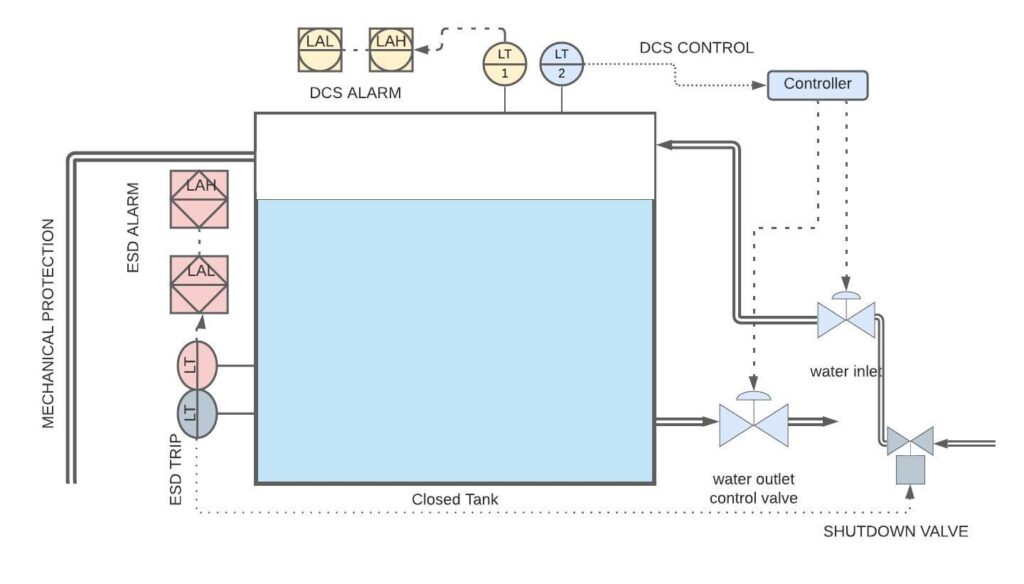
In all industries, there will be high-pressure vessels, high-temperature furnaces, tons of process liquid containing hazardous gas flowing through the pipeline, etc. Which may drastically affect the environment and sometimes endanger the life of a working person. In order to preserve them, we cant able to shut down all industries. The industry produces many useful things for living like electricity, cooking gas, vehicle fuel, food products, etc. But we can able to avoid accidents and reduce the risk to the maximum extend by implementing safety instrumented system protocol. The diagram given below will clearly explain the implementation of sis in the industry.

Process control is the first layer of defense in any industry. For example, if the pressure of the vessels gets increases the transmitter will sense the pressure increase and send a signal to the controller, and the control valve reacts respectively to the controller command. In the above diagram, DCS is the process control. I have mentioned it as it’s used in most of the industry. In case the DCS control fails, another transmitter or switch connected to the same line will alert us by alarm or trip the source to eliminate the hazard. Up to this level of protection is followed in all organization, but if these instruments failed we cant able to control the failure, so additional instruments isolated from the process control instruments helps to increase the risk reduction. From the example below I will clearly explain how its implemented.
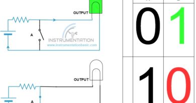
note: Compare colour of both image to identify the protection layers.
The tank level is controlled by the two control valves as see in the above diagram. In normal operation, the level is maintained by the means of opening and closing the valve without interruption. In case the control valve gets failed or the transmitter gets failed there is a chance of overflow of the tank. In order to eliminate the risk DCS alarm will notify the operator by means of an annunciator panel, siren, lamp, etc. helps us to identify the problem in a short span of time and implement the correction method immediately. If both the instruments failed sis act as an extra protective layer to eliminate the hazard. If all instruments failed at last the water will flow through the overflow pipeline. Thus the maximum protection is achieved over the whole process, this is how safety instrumented system works.
| Case 1 | control valve failed | 1.level may rise or fall intimate by DSC and Esd alarm 2.ESD valve and mechanical protection live |
| case 2 | DCS transmitter failed | DCS alarm, ESD valve, and mechanical protection live |
| case 3 | ESD transmitter failed | The process won’t get disturbed |
| Case 4 | both transmitter failed | DCS ESD alarms, ESD valve, and mechanical protection live |
| case 5 | All instruments failed | Mechanical protection |
Probability of failure on demand (PFD)
This factor helps us to identify the failure rate of every instrument when needed. Its normally denoted by 1* 10 -1 means the instrument failure rate is one time per 10 operations. For example, the control valve has 1*10-3 PFD, the chance of failure is 1 time over 1000 operation. At the starting of any project, the probability of failure is analyzed and instruments, logics, redundancy, etc are selected according to the hazardous area.