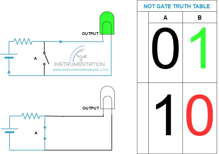
Not Gate Truth Table
This gate function is opposite to the input applied. If the input to the gate is true then the output lamp will not turn on. If we off the switch the lamp will ON. As you see in the diagram the circuit the NOT gate truth table was created using a simple wiring diagram.

You may wonder where we can use this type of gate in logic. For example, the instrument may go to i/o bad condition due to an error in the instrument or under/over range value. In such a case, we can’t able to use the value to control the process, in such case the signal from the quality block will be given through the NOT gatekeeping logic 1 in the off state. In case of a bad signal, the not gate input 1 will turn into 0.
Thus NOT gate truth table is useful for various such conditions to report a false state is actually a healthy one.


