Digital module basics
The digital module process the true/false status of the instrument by sensing the presence or de-presence of the voltage. The electric supply passed from the module is stop at one end of the device like a switch and when the switch is activated the contact get closed reaches the module. By which the signal is transferred to the controller, it displays the output as per the logic written. Let’s see the working of digital input and output module function separately. So you will get a clear idea of the function happening.
Digital Input Module
The digital input module senses the status of instruments like a switch, proximity sensor etc. Using sending the voltage signal towards one pair of cable and the circuit will get closed by the device in the field when activated or deactivated based on the contact taken. And when they return supply is sensed by the module, the condition will get changed in the sudden display. According to the logic predefined in the controller.The digital signal is used in process control for the following reasons.
Used as an interlock to start/ stop an equipment. To know the feedback of the device [open / close ] to drive the trip circuit in case of emergency
- To notify the operator by Low / high alarms.
- Used as an interlock to start/ stop equipment.
- To know the feedback of the equipment (open/close)
- Drive the trip circuit in case of emergency.
For example, the open command is given to the solenoid to operate a pnematic cylinder. In order to know the condition of the cylinder the limit switch is fixed at both end of the cylinder. It may be a mechanical driven switch or magnetic pickup but the concept is same. If the cylinder is fully open the switch will be activated and the contact change lead to closing the circuit. By which the digital module senses the open position with voltage presence. Send it to the controller and finally, it will get a display on the SCADA screen. Some the instruments used in industry used for this purpose is mention below.
- Limit switch
- Proximity switch
- Magnetic pickup
- Pressure, temperature ,flow and level switches
Digital output module
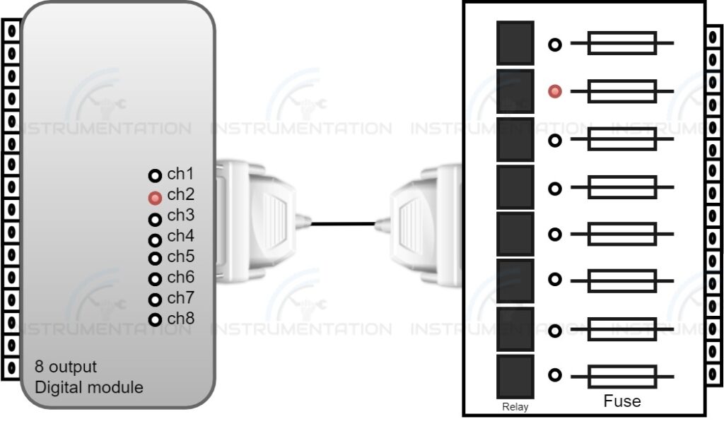
In the industry, the stop/start function of the equipment is done from the control room by sending the digital output signal to drive the contactor or relay by which the equipment is on/off in the field.
If you want to start/stop the motor, the motor required a supply voltage to be functional. The phase of the motor is switched directly or using a relay/contactor according to the capacity. In general digital output module itself is capable of handling voltage up to 230 V.
When the operator gives the start command to the motor. The digital module channel allotted will get energised the relay. By which the supply is taken through the channel will get closed reaches the motor and operates it. Similarly, if the operator gives the stop command channel relay will get de-energised by which the supply will get disconnected and the motor will get stopped. The digital output module is used for following reasons.
- Start/stop function
- Alarm/indication/siren
- Opening and closing valves