Closed Tank Level Measurement
In order to undergo Closed tank level measurement using a differential pressure transmitter, you need to find the lower and upper range values to configure the indirect level measurement. In order to find the range we need some basic detail like the specific gravity of the fluid used in the tank. The height of the tapping point etc.
The formula used for this calculation is,
∆P = ((SG1*H1)+(SG1*H3)) – (SG2*H2)
Closed Tank at zero level (dry leg)
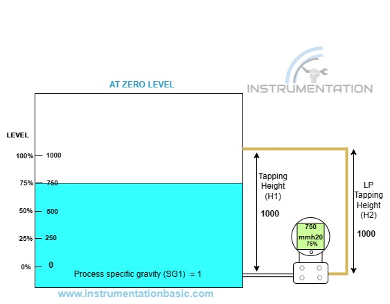
Now let’s consider a closed tank fill with the process fluid, at the empty level condition the fluid will be below the HP tapping point, so there will not be any pressure acting towards the HP side.
Let’s consider an example of a closed tank with a fluid used for the process, the tapping height of the tank is 1000, and dry leg tapping of the tapping height is 1150. And the specific gravity of the process liquid is 1. In order to find the range for the transmitter, apply the value in the above formula.
At empty condition (0% level)
LRV=(SG1*H1)-(SG2*H2)
LRV =(1*0) -(0*0)
LRV= 0
As the water level is below the tapping point no pressure acted toward the HP side.
We can find from the result the dry leg with fluid at normal conditions will act as a simple open tank. In case the process liquid change by temperature than the LP leg will compensate for the pressure change created by vapor.
At full condition (100% level)
URV=(SG1*H1) – (SG2*H2)
URV = (1* 1000) – (0*1050)
URV = 1000
As no vapor pressure in this condition, no pressure will be acted towards the LP side.
Zero Suppression (Dry Leg)
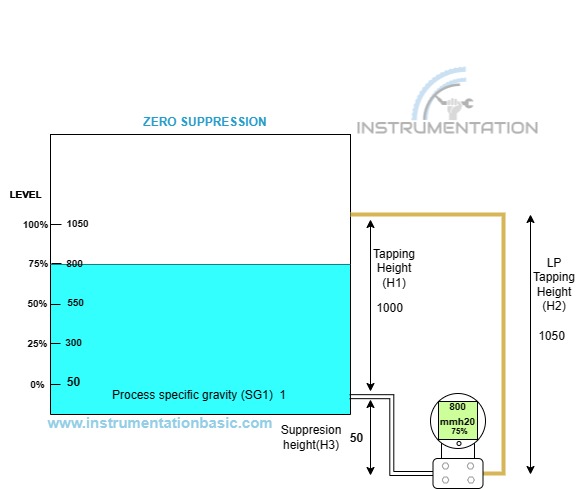
If the tapping point of the transmitter is taken above the zero level of the transmitter it is said to be zero elevation. Similarly, the tapping point of the transmitter is taken below the zero level of the transmitter it is known to be a zero suppression. In case you got confused about the elevation or suppression this point will help you to differentiate between both. If the positive pressure is acting toward the hp side at the tank empty level then it is said to be a suppression.
Now we will get a better understanding after solving the equation, let’s consider the close tank of tapping height 1000. If the tapping point of the transmitter is taken below zero level, the suppression height is 50. And the LP tapping height is 1200 and as we saw in the tapping point zero level condition the LP compensation leg is useless if the process liquid didn’t change its state.The closed tank level measurement is computed by the formula below.
At empty condition (0% level)
∆p=((SG1*H1)+(SG1*H3)) – (SG2*H2)
LRV = ( ( 1*0)+(1*50)-(0*0)
LRV= 50
At full condition (100% level)
URV = ((1* 1000)+(1*50)) – (0*0)
URV = 1050
Zero Elevation (dry leg)
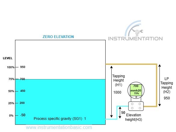
One difference is tapping point is taken above the empty level. If the water level rises up to an elevated height the transmitter will read still zero level, which will result in an inaccurate reading. So it is important to scale the elevated height, but normally this kind of practice needs to be avoided. In most cases, the transmitter is always mounted below the tank level. Let’s calculate the LRV and URV for the zero elevated tappings.
Let’s take the same value used for zero suppression the only difference is here the tapping point is elevated. The results will be
At empty condition (0% level)
∆p=((SG1*H1)-(SG1*H3)) – (SG2*H2)
LRV = ( ( 1*0)-(1*50)-(0*0)
LRV= -50
At full condition (100% level)
URV = ((1* 1000)-(1*50)) – (0*0)
URV = 950
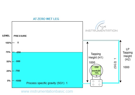
Closed tank level Measurement (Wet leg)
The difference between wet and dry legs is the LP side of the transmitter will always fill with the process liquid or standard liquid like glycol, which acts as a barrier between the process fluid and the transmitter sensor, thus preventing the sensing part from damage. And by using the wet leg impulse line chock is avoided. If a line carries a slurry liquid then the possibility of heavy particles may block the impulse line, by filling the impulse line with liquid greater than the density of process fluid this issue is eliminated.
And also the process liquid may change its state for certain temperatures and get condensed in the LP side of the transmitter to form the wet leg. So it is very important to take the height of the LP side into consideration while calculating the range. In the dry leg, LP side will not impact the level measurement as you have observed in the above examples.
At empty condition (0% level)
∆p= (SG1*H1) – (SG2*H2)
LRV = ( ( 1*0) -(1*1000)
LRV = 0 -1000
LRV= -1000
At full condition (100% level)
URV = (1* 1000) – (1*1000)
URV = 0
If you compare the result with the dry leg the value have reversed toward negative value due to the liquid in LP side.
Zero Suppression (Wet leg)
In the wet leg, the LP side of the transmitter is always filled by process liquid or solutions for certain reasons. In over temperature process sudden charging of the line may result in damage to transmitter parts, in such case the pressure will not directly impact if already a liquid is filled. And also the fluid will be converted into vapor and get condensation along the LP leg of the transmitter to form a wet leg. So this additional pressure has to be eliminated in order to scale the transmitter to exact zero level
Let’s take the same value used
At empty condition (0% level)
∆p=((SG1*H1)+(SG1*H3)) – (SG2*H2)
LRV = ( ( 1*0)+(1*50)-(1*1050)
=50-1050
LRV= -1000
At full condition (100% level)
URV = ((1* 1000)+(1*50)) – (1*1050)
URV = 0

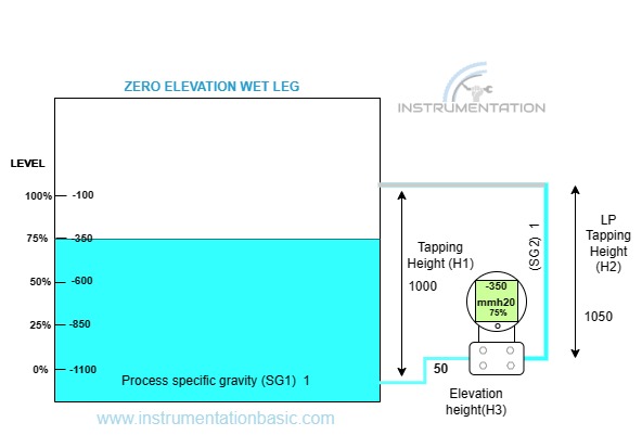
Zero Elevation (wet leg)
Similarly consider the same value used in the previous example.
At empty condition (0% level)
∆p=((SG1*H1) – (SG1*H3)) – (SG2*H2)
LRV = ( ( 1*0) – (1*50)-(1*1050)
LRV = -50-1050
LRV = -1100
At full condition (100% level)
URV = ((1* 1000) – (1*50)) – (1*1050)
URV = 1000 -50 -1050
URV = -100
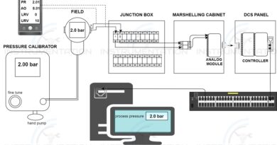
This calculator is designed in such a way that if you enter all the detail in the entry field. It will compute the calculation and displays the LRV and URV value Elevation (wet leg)

