Analog module basic
The analog module process both the incoming and outgoing signal from/to DCS. It is effective communication to get the value of the physical variable measured in the field. The physical variable like the pressure is transmitted over a large distance, the analog input module help to sense the electrical signal and display the current measured value help operator to monitor the process condition.
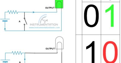
The signal range used for analog transmission is 4-20 MA. It is used a standard control signal in most of places. You may think why 0-20 ma is not used. To distinguish between the failure like cable cut or disconnect and physical measured zero value.
Analog input module
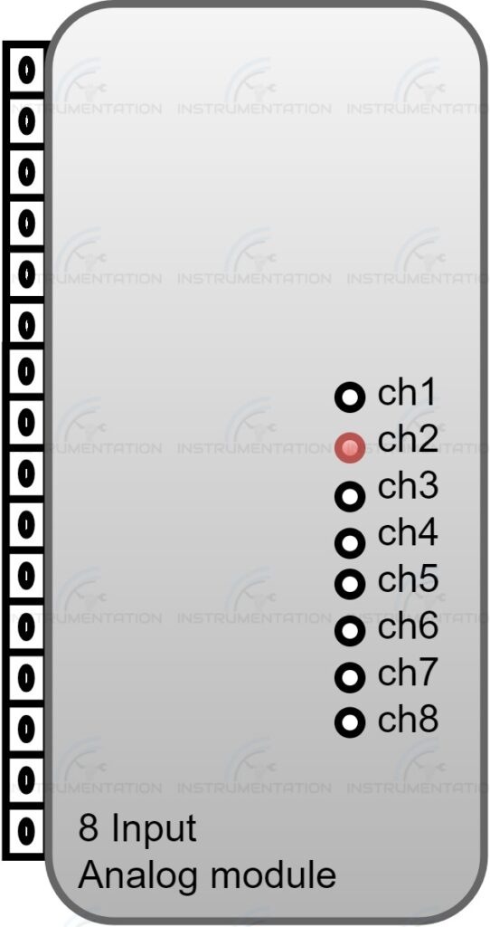
The analog input module process the signal coming from the instrument installed in the field. The analog module supplies the voltage to power up the instrument. The module provides the supply voltage of 24V in the case of a two-wire system. In four-wire, the instrument is powered by the external 230 v supply. And only the feedback analog signal is transmitted to the analog module. It senses the signal and transmits it to the controller. Finally, the raw value measured is displayed by SCADA.
- Transmitter(Pressure,flow,level etc.)
- Control value positioner
- Vibration transmitter
- Motorised valve position feedback
- The analyser (Ph, conductivity, silica etc.)
- Speed transmitter
- Linear variable displacement Transducer.
- Variable frequency drive ,Load cell, encoder etc.
These are some of the instrument you may see in the industry. The instrument output may be in mv, Hz, ohms etc. They are converted by the instrument before transferring to the analog module.
Analog output module
This is the control signal sent by the controller to the final control device in the field according to the process condition by which the whole process is maintained. For example, if the level of the tank is low. Need to fill the water to a normal level to stabilise the process. Then the controller will sense the current level through an analog input signal and send back the corrected output through the analog output module. The control valve I/P converter receives the signal and opens the valve desired to the command given.
- I/P converter
- Motorised valve inching valve
- VFD setpoint
Now you may get an idea about the analog module.The analog signal from DCS is referred to as analog output signal and the signal to DCS is called an analog input signal.