3500 Rack Configuration Simulator – Machinery Protection Training
Bently Nevada 3500 Rack Configuration Simulator – Machinery Protection System Training
The Bently Nevada 3500 series machinery protection system is widely used in industrial plants to monitor the condition of rotating equipment such as compressors, turbines, pumps and motors.
In critical machinery, monitoring vibration, shaft position, speed and bearing temperature is essential. Abnormal operating conditions must be detected early so that operators and maintenance engineers can take appropriate action before serious equipment damage occurs.
Understanding how to configure a 3500 rack is an important skill for instrumentation and reliability engineers.
The 3500 Rack Configuration Simulator provides a practical training environment to understand rack arrangement, module configuration, monitoring channels, alarm setpoints, relay logic and communication between configuration software and the protection rack.
What is a 3500 Machinery Protection System?
A 3500 machinery protection system is designed to monitor critical machine parameters and generate alarms when measured values exceed configured limits.
Typical parameters include:
- Shaft radial vibration
- Shaft position and probe gap
- Casing vibration
- Bearing temperature
- Machine speed
- Overspeed conditions
The system uses different monitoring modules depending on the measurement requirement. These modules are installed in a rack and configured to monitor the connected transducers.
Understanding the 3500 Rack Modules
Each module performs a specific function within the machinery protection system.
1. Power Supply – 3500/15
The power supply provides the required operating power to the rack.
Two power supplies can be installed to provide redundancy. This helps maintain rack operation if one power supply fails.
2. Rack Interface Module – 3500/20
The Rack Interface Module provides communication between the rack and configuration software through a serial interface. It also provides system reset and key-lock functions.
3. Transient Data Interface – 3500/22M
The Transient Data Interface provides rack communication through Ethernet and supports transient data collection.
The rack interface occupies the designated interface position in the rack.
4. Proximitor Monitor – 3500/40M
The 3500/40M is a four-channel monitor used with proximity transducers.
Typical applications include:
- Shaft radial vibration
- Shaft position
- Probe gap monitoring
The monitor compares measured values against configured Alert and Danger setpoints.
5. Proximitor/Seismic Monitor – 3500/42M
The 3500/42M supports proximity and seismic transducer applications.
It can be used for:
- Shaft vibration measurement
- Casing vibration measurement
- Velocity measurement
- Acceleration measurement
It is commonly used in machinery vibration monitoring applications.
6. Keyphasor Module – 3500/25
The Keyphasor module receives a once-per-revolution reference pulse from the Keyphasor transducer.
This reference is useful for machine speed and phase-related measurements.
7. Tachometer Module – 3500/50
The tachometer module monitors machine speed using speed pickup signals. It can also be configured for overspeed alarm applications.
8. Temperature Monitor – 3500/60
The temperature monitor accepts temperature inputs from thermocouples and RTDs.
Typical applications include bearing metal temperature and machine casing temperature monitoring.
9. Relay Modules – 3500/32 and 3500/33
Relay modules provide output contacts based on configured alarm drive logic.
For example:
- Alert alarm relay
- Danger alarm relay
- Not OK relay
- Logic based on multiple monitor conditions
Relay logic can use OR or AND conditions, depending on the required application.
10. Communication Gateway – 3500/92
The communication gateway transfers monitor information to external control systems. Modbus communication is one example of its application.
Understanding Alert and Danger Setpoints
One of the most important configuration tasks is setting the correct alarm limits.
Alert: The first alarm level. It indicates that a monitored parameter has reached an abnormal operating condition and requires attention.
Danger: The higher alarm level. It indicates a more serious condition that may require protective action.
For example, consider a vibration channel with these training setpoints:
- Alert: 2.5 mil pp
- Danger: 4.0 mil pp
When vibration reaches the Alert setpoint, the monitor indicates an Alert condition. When it reaches the Danger setpoint, the higher alarm condition is generated.
Actual setpoints must always be selected according to the machine manufacturer’s recommendations, applicable standards and approved protection study.
Alarm Delay and Latching
Alarm delay prevents short-duration signal spikes from immediately generating an alarm.
For example, if an Alert delay is configured, the measured value must remain above the Alert setpoint for the configured duration before the alarm is activated.
Latching is another important function.
- Nonlatching: The alarm clears when the alarm condition returns to normal.
- Latching: The alarm remains active until the appropriate reset action is performed, subject to the system’s reset conditions.
Understanding these settings is important when configuring machinery protection systems.
Understanding Relay Logic – AND and OR
Relay logic determines how monitor alarm conditions operate the relay outputs.
OR logic: The relay operates when any one of the configured conditions becomes active.
Example: A relay can be configured to operate when any selected vibration channel reaches Alert.
AND logic: The relay operates only when all configured conditions are active.
Example: A two-out-of-two arrangement can require two selected Danger conditions before the relay operates.
The actual protection design and voting arrangement must be checked against the approved cause-and-effect and machinery protection philosophy.
Rack Configuration: Upload, Download and Verify
Three important operations are used when working with rack configuration software.
Upload from Rack
Upload reads the configuration currently stored in the physical rack and transfers it into the configuration software.
This is useful when checking an existing installation or reviewing the current configuration.
Download to Rack
Download writes the configuration file from the software into the rack.
Before downloading, important checks include:
- Communication with the rack is available.
- The rack key lock is in PROGRAM.
- The configuration has no validation errors.
- The configured modules match the installed hardware.
- The required channel and relay settings are correct.
After downloading, return the key lock to RUN as required by the approved procedure.
Verify Configuration
Verify compares the configuration in the software with the configuration stored in the rack.
This helps identify differences between the offline configuration file and the rack configuration.
Practical Training Using the 3500 Rack Configuration Simulator
The simulator provides an interactive environment to practise common configuration activities.
You can explore the following functions:
1. Rack arrangement
Select rack slots and understand the position of power supplies, rack interface modules, monitors, relay modules and communication gateways.
2. Module configuration
Insert and configure different module types. Explore channel settings, transducer selection and measurement ranges.
3. Alarm configuration
Configure Alert and Danger setpoints, alarm delays and latching options.
4. Relay logic configuration
Create relay conditions using AND and OR logic. Explore relay actions such as energize on alarm and de-energize on alarm.
5. Rack communication
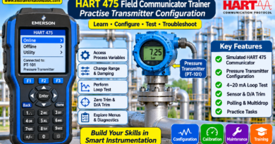
Practise connecting to the simulated rack, uploading configurations, downloading changes and verifying the configuration.
6. Live machinery simulation
Change machine speed, shaft vibration and bearing temperature using the simulation controls.
You can also introduce a proximity probe fault, disconnect the communication cable and activate Trip Multiply to observe the simulated system response.
7. Guided training
A 12-step guided tour takes you through rack selection, live rack view, communication, upload, alarm configuration, setpoint changes, relay logic, validation, download and verification.
You can also use Free Explore mode to investigate the available menus, fields and functions independently.
Practical Exercise: Compressor Vibration Monitoring
Consider a compressor train with proximity probes installed at the drive-end and non-drive-end bearings.
A typical training configuration may include:
- Drive-end X vibration
- Drive-end Y vibration
- Non-drive-end X vibration
- Non-drive-end Y vibration
- Alert and Danger setpoints for each channel
- Relay logic based on selected alarm conditions
Configure the monitor channels, assign the alarm limits and create relay logic.
Then increase the simulated shaft vibration and observe how the monitor changes from normal operation to Alert and Danger conditions.
This exercise helps explain the relationship between transducer measurements, monitor alarm processing and relay outputs.
Important Checks Before Downloading a Configuration
Before downloading any configuration to an actual machinery protection rack, verify the following:
- Confirm the correct rack and module arrangement.
- Check every enabled channel and transducer type.
- Verify measurement ranges and engineering units.
- Confirm Alert and Danger setpoints.
- Check alarm delays and latching settings.
- Review relay alarm drive logic.
- Confirm communication settings.
- Validate the configuration and resolve errors.
- Confirm configured modules match installed hardware.
- Follow the approved download and commissioning procedure.
Never perform live protection testing or change trip-related settings on operating machinery without the required authorization, risk assessment and approved bypass or testing procedure.
Conclusion
Understanding 3500 rack configuration is an important part of machinery protection system maintenance and commissioning.
Instrumentation engineers should be familiar with monitor modules, transducer selection, alarm setpoints, relay logic, rack communication and configuration verification.
This simulator provides an opportunity to practise these concepts in a simulated environment before working with an actual machinery protection system.
Note: This is an independent educational training simulator. It is not official Bently Nevada software and does not communicate with real 3500 hardware. Menu names and configuration behaviour are representative training examples; actual software versions and hardware configurations may differ.